Litz Wire Calculation & Design
Litz Wire & Cable Construction(=Design)
Bundled directly
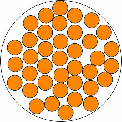
Several single wires are tied directly, so each individual wire is freely laid out. In further bundling operations, multiple sub-bundle wires can be combined to create a larger litz structure. Each bundle structure can be more differentiated. Through the length of the ray(tightness of the twist) and pitch direction(twist direction).
Bundled concentrically
The individual wires are placed in one or more layers concentrically around the litz wire center conductor. In this design configuration, each single wire naturally moves to a predefined location during twisting to provide consistent dimensions and working characteristics.
 1st-step-construction
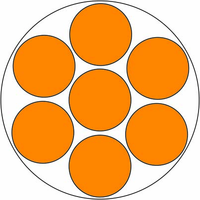 multi-step-concentric-construction
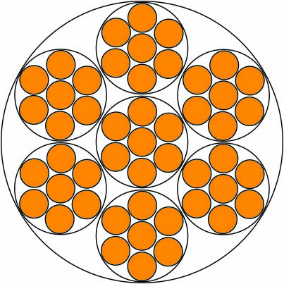 concentric-construction
Please click each of the Taps below.
Pitch calculation and lay direction of litz wire
Designing construction and Calculating of litz-wire
To calculate 'same cross-section area or same surface area' of litz wire
Enhancing method of Q factor & Inductance value
Calculating square meter for Silk & Nylon requirement on litz wire's surface
1. Pitch calculation
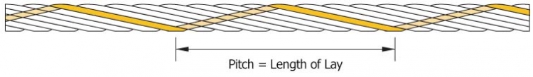 Litz wire pitch
The lay length shows the interval which a single wire needs for one complete turn(=rotation) around the litz wire perimeter(360 degrees).
The term refers to the distance required by the “length of lay (=pitch)” (See above drawing) which can be turned 360° to one line of. Standard EN 60317-11 is recommended to provide 60 mm, the maximum length of lay for served litz wire. However, actually, the length of the lay is from 0.80 mm up to 60 mm. (0.4 twists per inch/5 twists per foot, 32 twists per inch)
ex 1) Regarding 4 strands x 0.63mm,
The OD(=Outer Diameter) for 4 x 0.63mm is approximately 1.45mm. (using your formula). This gives a lay length of 36.25mm which equates to 28 twists per meter, however, it should be used 54 twists per meter for working well at this configuration.
–> 4 x 0.63.
√4 x 1.154 x ( 0.63 + enamel coating thickness )od = approx. 1.45mm
lay length = 25 x OD 1.45 = 36.25mm 1000 / 36.25 = about 28 x 2 = 54 required on actual application in order to afford
ex 2) With regard to pitch,
Suggested lay length should be 25 x OD(=Outer Diameter)
For instance, regarding 150 strands x 0.100 mm
The OD for 150 x 0.118 mm ( od including insulation, gr1 of copper wire 0.100mm )
approximates to 1.67 mm ( √150 x 1.154 x 0.118 )
This gives a lay length of 41.75mm which equates to 23.95 (≒24) twists per meter, however, in fact customers has applied for 48 twists per meter. Because the material is working well under 48 twists. So, that is, 25 x OD x 2 times.
2. Lay(=pitch) direction
 Click to enlarge!- litz wire lay direction
The specific parameters of litz wire should be exist as well as the length of the lay(=pitch) by “S” or “Z” direction. The lay direction typically indicates the direction of the litz wire twisted and laid in two different directions like the left direction “S” or the right direction “Z”.
ref. Pitch no. of litz wire might be decreased to reduce self-heat affect.
The calculation of net weight to litz wire
● gram/meter = od2 x number of strands x 7
od2: Bare diameter + insulation
7: Copper wire’s constant(=specific gravity)
FYR, actual specific gravity of Cu = 8.92 / Al = 2.71 / Fe = 7.85
The calculation of outer diameter to litz wire
● OD(mm) = √N x 1.154 x d(mm)
N: Number of conductors (including coated thickness, 0080mm –> 0.087mm etc.)
d: Diameter of a conductor
OD: Outer diameter of Litz wire
Outer diameter after covering : single served (SSC, USTC)
● OD + (0.02 to 0.04mm) x 2
The calculation of conductivity for changing Cu(copper) to Al(aluminum)
● ex. If you need to change Cu(0.25mm) to Al, what OD Al is.
(Cu(0.25mm)÷2)² x π = approx. 0.049㎟
0.049㎟ x 1.61(61% increasing) = approx. 0.79㎟
Al wire outer diameter of 0.079㎟(cross section) is 0.32mm.
The wire gauge choosing as frequency (Table 2.)
| Frequency | Recommended wire gauge | OD(mm) | D.C. Resistance Ohms/M’(Max) | Single Strand RAC / RDC “S” |
|---|---|---|---|---|
| 60 HZ to 1 KHZ | 28 AWG | 0.32 | 66.37 | 1.0000 |
| 1 KHZ to 10 KHZ | 30 AWG | 0.25 | 105.82 | 1.0000 |
| 10 KHZ to 20 KHZ | 33 AWG | 0.18 | 211.70 | 1.0000 |
| 20 KHZ to 50 KHZ | 36 AWG | 0.12 | 431.90 | 1.0000 |
| 50 KHZ to 100 KHZ | 38 AWG | 0.10 | 681.90 | 1.0000 |
| 100 KHZ to 200 KHZ | 40 AWG | 0.08 | 1152.3 | 1.0000 |
| 200 KHZ to 350 KHZ | 42 AWG | 0.06 | 1801.0 | 1.0000 |
| 350 KHZ to 850 KHZ | 44 AWG | 0.05 | 2873.0 | 1.0000 |
| 850 KHZ to 1.4 MHZ | 46 AWG | 0.04 | 4544.0 | 1.0003 |
| 1.4 MHZ to 2.8 MHZ | 48 AWG | 0.03 | 7285.0 | 1.0003 |
The formula of Hysteresis loss(Ph)
– hysteresis loss calculation
f = frequency (Hz)
v = core volume [㎥]
h(a constant) = coefficient of hysteresis
Bm1*6 = alternating magnetic flux density
The formula of Eddy current loss calculation (Pe)
 Click to enlarge!
– eddy current loss calculation
f = frequency
k = conductivity
t = core thickness (usually 0.3~05.mm)
Bm = alternating magnetic flux density (ex. 1.6~2 –> Bm1.6~2)
 Click to enlarge!
– iron loss calculation
Ironloss = hystrersis loss(Ph) + eddy current loss(Pe)
Regarding litz wire designing and calculation
Design engineers to use the litz typically know their frequency of operation required by the application, and RMS current. The main advantage of the litz-conductor AC loss reduction because the first thought of any litz-design is the frequency of operation. It is also, as well as the frequency of operation affect the structure of a full-fledged litz individual is determined by the wire gauge. DC resistance ratio of the flow resistance values (X) in terms of the isolated solid round wire (S) are shown in Table 1.
Table1
| X | 0 | 0.5 | 0.6 | 0.7 | 0.8 | 0.9 | 1.0 |
| S | 1.0000 | 1.0003 | 1.0007 | 1.0012 | 1.0021 | 1.0034 | 1.005 |
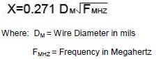
Copper wire, the value of X is determined by the equation 1.
Litz structure of most other real-world data, in Table 1 for the recommended wire gauge for frequencies in the following table.
 Click to enlarge!
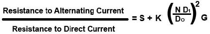
If the architectural design would be assumed the sutable litz construction and the individual wire gauge has been determined. Each strand is tended to be inhabited almost the same extent in all possible positions of the cable. Remote litz conductor of D/C ratio of AC resistance can be determined by the following equation.
 Click to enlarge!
Where: S = Resistance ratio of individual strands when isolated (taken from Table 1 or 2)
G = Eddy Current basis factor =
 Click to enlarge!
F = Operating Frequency in HZ
N = Number of strands in the cable
D1 = Diameter of the individual strands over the copper in inches
DO = Diameter of the finished cable over the strands in inches
K = Constant depending on N, given in the following table:
| N | 3 | 9 | 27 | Infinity |
| K | 1.55 | 1.84 | 1.92 | 2 |
Litz-conductor DC resistance is associated with the following parameters:
1) Individual strands of AWG.
2) The number of the strands of the cable.
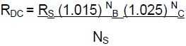
3) Factors related to the increase in length per each strand (forward) unit length of the cable. About a 2.5% increase in DC resistance, DC resistance for all bundle tasks for standard Ritz structures, and an increase of 1.5% for all cabling to make sure that they are correct. The DC resistance of the construction of any litz formula is derived from the parameters:
 Click to enlarge!
The following is an example of the calculations needed to evaluate the construction of a single film, polyurethane coating 38 AWG Litz wire strand consisting of 400 operating at 500 kHz. Will record this construction design, the cable bundle two 5 × 5/40 16 AWG
1) Calculated using the formula 3, the DC resistance of the litz construction.
 Click to enlarge!
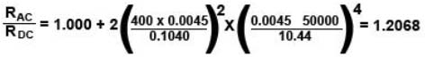
2) AC to DC resistance ratio is calculated using the formula 2.
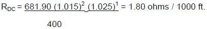 Click to enlarge!
3) AC resistance is, therefore, 1.2068, or 1.80 ohms/1000ft(=304.8m).
Litz wire manufacturer has been requested to supply AWG size no other than mm (millimeter) scale. For example AWG36=0.127mm(including enamel coated OD), that is, single strand section area (= 0.0126677mm sq.) and if we use the similar size 0.120mm single strand section area (= 0.0113097mm sq.) of AWG36. When customer asks for AWG36 x 1,000 strands, the total section area gives 0.0126677 mm sq. x 1,000 strands = 12.6677mm sq.
If we use 0.120mm wire, 12.6677mm sq / 0.0113097mm sq. = 1120 strands.
Therefore, we can use either AWG36 x 1,000 strands or 0.120 mm x 1,120 strands for the wire to have the same current carrying capacity, but 0.120mm x 1,120 strands will show more better skin effect performance than AWG36 x 1,000 strands because single 0.120mm is better skin effect performance than 0.127mm(AWG36).
1,000 strands x AWG36 gives 1,120 strands of 0.120mm ( or close to 1,125 strands = 5 x 5 x 45 strands ).
UL says “temperature rise” shall be 75 deg. C less on A Class, and 95 deg. C less on B Class and we have often faced “temperature rise problem” when we develop a transformer at R&D step. To solve “temperature rise (= delta T, which mean excluded ambient temperature)”, we can decrease the exceeded high temperature rise on UL standard, just as building much strands.
1. ‘Q factor’ enhancing method
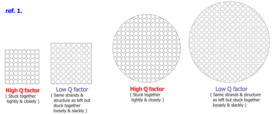
In physics and engineering, quality factor or Q factor is a dimension-free parameter. It is decided by showing whether or not to give us its status, low-attenuated vibration or resonator. Also, the bandwidth of the resonator according to the center frequency is determined. The high Q factor means lower energy losses than the energy stored in the oscillator as well the vibration is slowly reduced as in this case. The vibrating pendulum in the air hanging the high quality bearing has high Q factor. On the other hand, the vibrating pendulum immersed in oil has low Q factor. High Q factor’s oscillator has lower braking and longer vibrating.
In order to enhance Q factor value of litz wire and cable, you should wind litz wire stuck together tightly as maximum adhesion between copper wire and copper wire as following image, ref. 1.
 high Q factor enhancing method
When we design electronic products, Q factor is an important variable. It decides the bandwidth of resonator according to the center frequency as well as the high Q factor should be designed to lower energy losses compared to the energy stored in the vibrator. In other words, the vibration reducing should be slow.
Q= X/R= шL/R= 2∏fL/R
– Q : Quality factor
– X : reactance is by the resistance value of the coil inductance
– R : resistance is by the resistance value of the coil.
– f : resonance frequency.
– ∏ : circular constant(pi), 3.14……
2. The method to raise the ‘Inductance value’ is as following.
Manufacturing litz wire as ‘tight & stick’ as possible. The magnetic flux density is re-doubling by locating a ferromagnetic core in the inner coil. Increase of the magnetic flux density also results in an inductance increasing. Therefore, the inductance value of ferromagnetic core is several times larger than of the air coil or nonmagnetic core as plastic and wood etc. Inductance value is functions depending on the number of revolutions of the coil winding, the diameter of the coil, and the overall shape of a coil. Inductance of the coil is directly proportional to the rotation speed (number of turns) wound wire and is directly proportional to the inductance of the coil diameter. More accurately, inductance of the coil in the solenoid coil per unit length is directly proportional to the cross-sectional area and directly proportional to the squared of revolutions wound wires per unit length. It affects the inductance value in case of providing constantly the revolutions and diameter of the coil as well as coil’s length. If pulling out the coil with a constant number of revolutions and diameter by increasing the length, the inductance value of the coil is reduced. Contrary, if the coil would be compressed to make it flat, the inductance value of the coil will be increased. In case of litz wire, if the frequency increases, the inductance value goes up.
To enhance Q- factor & Inductance value in case of litz wire, each wire can be stuck together very tightly by self-bonding fabricating and controlling pitch calculation. Therefore, litz wire shall be built through served possibly many times on wires and higher temperature building on final serving step and then higher Q value will be got.
3. Depending on the Inductance direction as following.
The inductance increases as flowing in the same direction as No. 1 picture. L(inductance)=L1+L2
The inductance offesets as flowing in the opposite direction as No. 2 picture. L(inductance)=L1-L2
Therefore, No. 1 is generally used for increasing L value.
 mutual inductance
We would like to explain ‘Required raw material calculation’ of Silk or Nylon’ to customers as following. The calculation of square meter is of great help at main production stage by predicting requirements of the raw material costs.
1) For example, 0.05mm x 1,000 strands with double served,
– OD= √1,000 x 1.154 x 0.062mm(thickness including enamel coating)= approx. Φ2.5mm(including silk or nylon thickness)
– S(square meter)= Φ2.5mm x π = approx. 7.6㎟
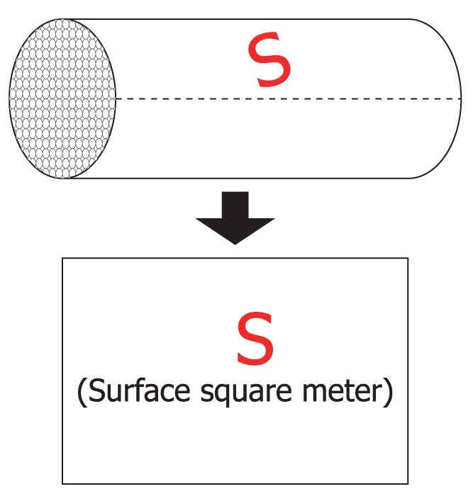 calculation of square meter for silk & nylon on litz wire
2) In case of 0.05mm x 1,680 strnads with single served, the weight of nylon is approx. 32g/m(actual measurement).
– The requirement volume of ‘0.05mm x 1,000 strands’ is calculated to approx. 19.2g/m by equation.
– 19.2g/m x 2(in case of double served)= 38.4g/m
– If you want to know ( )m per kg, X = 1,000 strnads x 1m / 19.2 = 52.08m/kg –> 100kg= 5,208m
3) In case of 0.05mm x 1,000 strands with double served, you need to calculate its square meter as following.
– 0.0076m(1m square meter of 0.05mm x 1,000 strands) x 5,208m(the amount of silk or nylon wound on 100kg litz wire)= S = 39.58㎡(Surface area of 100kg litz wire)